
Rectangular to Polar Circuits: AC Impedance, Phasors & Electrical Analysis
Master rectangular to polar circuits conversion in AC electrical engineering. Convert impedance Z = R + jX to polar form |Z|∠θ, calculate phasors, and solve AC circuits.
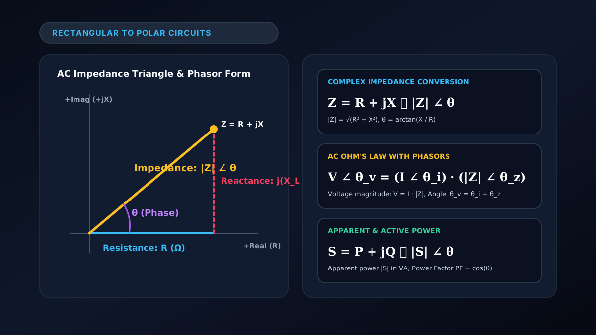
In AC electrical engineering, rectangular to polar circuits conversion transforms complex electrical quantities—such as impedance ($Z = R + jX$), voltage phasors ($\mathbf{V} = V_{\text{real}} + jV_{\text{imag}}$), and current phasors—from rectangular form into polar form ($|Z|\angle\theta$ or $V\angle\theta$). Converting to polar form simplifies multiplication and division operations required for AC Ohm’s Law ($\mathbf{V} = \mathbf{I} \cdot \mathbf{Z}$) and power calculations.
Figure 1: Impedance triangle representation and phasor transformation equations in rectangular to polar circuits.
Working with alternating currents (AC) means voltages and currents oscillate sinusoidally. Using complex phasor notation allows engineers to treat dynamic AC circuits with the same straightforward algebraic techniques used in DC circuits. You can convert impedance values instantly on our online rectangular to polar calculator or use our circuit calculator guide.
Why Coordinate Conversions Matter in AC Circuit Analysis
In alternating current networks containing resistors ($R$), inductors ($L$), and capacitors ($C$), the relationship between voltage and current depends on both magnitude and phase shift:
- Rectangular Form ($Z = R + jX$):
- Ideal for addition and subtraction (e.g., finding the total series impedance of components: $Z_{\text{total}} = Z_1 + Z_2 = (R_1 + R_2) + j(X_1 + X_2)$).
- Polar Form ($Z = |Z|\angle\theta$):
- Ideal for multiplication and division (e.g., calculating AC Ohm’s Law: $\mathbf{I} = \frac{\mathbf{V}}{\mathbf{Z}} = \frac{V\angle\theta_v}{|Z|\angle\theta_z} = \frac{V}{|Z|}\angle(\theta_v - \theta_z)$).
Core Conversion Formulas for AC Circuits
To convert an impedance $Z = R + jX$ into polar notation $|Z|\angle\theta$:
1. Impedance Magnitude ($|Z|$)
The total impedance magnitude (in Ohms, $\Omega$) represents the hypotenuse of the impedance triangle:
$$|Z| = \sqrt{R^2 + X^2}$$
Where:
- $R$ = Resistance (Ohms, $\Omega$, real part, always $R \ge 0$).
- $X$ = Net Reactance ($X_L - X_C$, imaginary part in Ohms, $\Omega$).
- Inductive reactance: $X_L = 2\pi f L = \omega L$ ($+j$ component, voltage leads current).
- Capacitive reactance: $X_C = \frac{1}{2\pi f C} = \frac{1}{\omega C}$ ($-j$ component, voltage lags current).
2. Phase Angle ($\theta$)
The phase angle $\theta$ measures the phase lead or lag between voltage and current:
$$\theta = \arctan\left(\frac{X}{R}\right)$$
- If $X > 0$ (Inductive circuit): $\theta$ is positive (voltage leads current, lagging power factor).
- If $X < 0$ (Capacitive circuit): $\theta$ is negative (current leads voltage, leading power factor).
- If $X = 0$ (Purely resistive circuit): $\theta = 0^\circ$ (voltage and current are in phase).
AC Circuit Phasor Transformations Table
| Circuit Type | Rectangular Impedance ($Z$) | Polar Impedance ($|Z|\angle\theta$) | Phase Relationship | | :--- | :--- | :--- | :--- | | Pure Resistor | $Z = R + j0$ | $Z = R \angle 0^\circ$ | In-phase ($\theta = 0^\circ$) | | Pure Inductor | $Z = 0 + jX_L$ | $Z = X_L \angle +90^\circ$ | Voltage leads by $+90^\circ$ | | Pure Capacitor | $Z = 0 - jX_C$ | $Z = X_C \angle -90^\circ$ | Voltage lags by $-90^\circ$ | | Series R-L Circuit | $Z = R + jX_L$ | $Z = \sqrt{R^2 + X_L^2} \angle \arctan(X_L / R)$ | Voltage leads by $0^\circ < \theta < 90^\circ$ | | Series R-C Circuit | $Z = R - jX_C$ | $Z = \sqrt{R^2 + X_C^2} \angle \arctan(-X_C / R)$ | Voltage lags by $-90^\circ < \theta < 0^\circ$ | | Series R-L-C Circuit | $Z = R + j(X_L - X_C)$ | $Z = \sqrt{R^2 + (X_L - X_C)^2} \angle \arctan(\frac{X_L - X_C}{R})$ | Net inductive ($X_L > X_C$) or capacitive ($X_C > X_L$) |
Step-by-Step Solved AC Circuit Example
Problem Statement:
An AC circuit operates at $60\text{ Hz}$ connected to a voltage source $\mathbf{V} = 120\text{ V}\angle 0^\circ$. The load consists of a resistor $R = 40,\Omega$ in series with an inductor with reactance $X_L = 30,\Omega$.
- Find the total impedance in polar form.
- Calculate the circuit current phasor $\mathbf{I}$.
- Determine the power factor ($\text{PF}$).
Solution:
Step 1: Convert Rectangular Impedance to Polar Form
- Rectangular form: $Z = 40 + j30,\Omega$
- Magnitude: $|Z| = \sqrt{40^2 + 30^2} = \sqrt{1600 + 900} = \sqrt{2500} = 50,\Omega$
- Phase angle: $\theta = \arctan\left(\frac{30}{40}\right) = \arctan(0.75) \approx 36.87^\circ$
- Polar Impedance: $\mathbf{Z} = 50,\Omega \angle 36.87^\circ$
Step 2: Apply AC Ohm’s Law for Current Phasor
$$\mathbf{I} = \frac{\mathbf{V}}{\mathbf{Z}} = \frac{120\text{ V}\angle 0^\circ}{50,\Omega\angle 36.87^\circ} = \left(\frac{120}{50}\right)\angle (0^\circ - 36.87^\circ) = \mathbf{2.40\text{ A}\angle -36.87^\circ}$$
The current magnitude is $2.40\text{ A}$, lagging the source voltage by $36.87^\circ$.
Step 3: Determine the Power Factor
$$\text{PF} = \cos(\theta) = \cos(36.87^\circ) = 0.80\text{ (Lagging)}$$
Complex Power Conversions: Apparent, Active & Reactive Power
Rectangular to polar conversion is equally vital for AC electrical power:
$$\mathbf{S} = P + jQ \implies |\mathbf{S}|\angle\theta$$
- Active Power ($P$): Real power in Watts ($\text{W}$) that performs physical work ($P = |\mathbf{S}|\cos\theta$).
- Reactive Power ($Q$): Imaginary power in Volt-Amps Reactive ($\text{VAR}$) stored in magnetic/electric fields ($Q = |\mathbf{S}|\sin\theta$).
- Apparent Power ($|\mathbf{S}|$): Total magnitude in Volt-Amps ($\text{VA}$), where $|\mathbf{S}| = \sqrt{P^2 + Q^2}$.
Engineering Software & Web Tools
For electrical engineering consulting, custom hardware modeling software, or specialized web calculators, learn more about the custom development services at Shahab Dev.
Frequently Asked Questions (FAQ)
What does rectangular to polar circuits conversion mean?
It means transforming AC circuit quantities expressed in rectangular form (like impedance $R + jX$ or complex power $P + jQ$) into polar phasor form ($|Z|\angle\theta$ or $|S|\angle\theta$) to simplify AC circuit analysis and Ohm’s law division.
Why is the imaginary operator written as ‘$j$’ in electrical circuits instead of ‘$i$’?
In electrical and electronics engineering, the letter $i$ is universally reserved for instantaneous electrical current ($i(t)$). To avoid confusion, engineers use $j = \sqrt{-1}$ for the imaginary unit.
How do I calculate total parallel impedance using rectangular and polar forms?
For two parallel branches $Z_1$ and $Z_2$, use the formula $Z_{\text{parallel}} = \frac{Z_1 \cdot Z_2}{Z_1 + Z_2}$. Convert to polar form for the numerator multiplication ($Z_1 \cdot Z_2$), keep rectangular form for the denominator addition ($Z_1 + Z_2$), then convert the sum to polar form to perform the final division.
How can I calculate circuit phasors on my scientific calculator?
Scientific calculators like Casio and TI models have complex modes (CMPLX) where you can enter numbers in $a+bi$ format and convert them to $r\angle\theta$. See our guide on how to convert rectangular to polar in Casio calculators.