
Rectangular to Polar Calculator Circuits: AC Phasor & Impedance Solvers
Learn how to use a rectangular to polar calculator for circuits. Compute AC voltage, current phasors, complex impedance, and power factor with speed and precision.
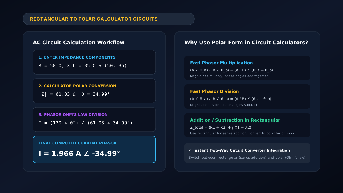
A rectangular to polar calculator for circuits is an indispensable engineering tool designed to solve AC electrical network problems involving complex numbers. It instantly converts rectangular impedance ($Z = R + jX$) into polar phasors ($|Z|\angle\theta$), allowing electrical engineers and students to compute AC current $\mathbf{I} = \frac{\mathbf{V}}{\mathbf{Z}}$, node voltages, mesh currents, and apparent power without tedious manual trigonometric steps.
Figure 1: Step-by-step workflow for calculating AC impedance and phasor currents using a circuit calculator.
When analyzing alternating current circuits, switching between rectangular and polar formats is essential: addition and subtraction are done in rectangular form, while multiplication and division are performed in polar form. You can perform instant impedance conversions on our free rectangular to polar calculator or read our foundational guide on rectangular to polar circuits.
Why Use a Rectangular to Polar Calculator in Circuit Analysis?
AC circuit analysis frequently requires solving complex linear equations. Here is why using a dedicated rectangular to polar calculator for circuits is critical:
- Simplifies AC Ohm’s Law: Dividing phasors manually in rectangular form requires rationalizing denominators by multiplying by complex conjugates: $$\mathbf{I} = \frac{V_1 + jV_2}{R + jX} = \frac{(V_1 + jV_2)(R - jX)}{R^2 + X^2}$$ With a polar calculator, division becomes a single instantaneous step: $$\mathbf{I} = \frac{V\angle\theta_v}{|Z|\angle\theta_z} = \left(\frac{V}{|Z|}\right)\angle(\theta_v - \theta_z)$$
- Instant Power Factor & Phase Determination: The calculated angle $\theta$ directly gives the circuit phase angle, from which power factor $\text{PF} = \cos(\theta)$ is immediately obtained.
- Eliminates Algebraic Sign Errors: Prevents negative tangent mistakes in inductive ($+j$) vs capacitive ($-j$) circuit branches.
How to Solve AC Circuits Using the Calculator: 4-Step Method
Follow this standard engineering procedure to analyze any AC circuit network:
[ Step 1: Calculate Reactances XL and XC ]
                    │
                    ▼
[ Step 2: Sum Series Impedances in Rectangular (R + jX) ]
                    │
                    ▼
[ Step 3: Use Calculator to Convert to Polar (|Z| ∠ θ) ]
                    │
                    ▼
[ Step 4: Divide Voltage by Impedance to Find Current (I ∠ θ_i) ]
Step 1: Compute Reactance Values
- Inductive Reactance: $X_L = 2\pi f L = \omega L$
- Capacitive Reactance: $X_C = \frac{1}{2\pi f C} = \frac{1}{\omega C}$
Step 2: Write Total Impedance in Rectangular Form
- For components in series: $$Z_{\text{eq}} = (R_1 + R_2 + \dots) + j(X_L - X_C)$$
Step 3: Convert $Z_{\text{eq}}$ to Polar Form with the Calculator
Enter real part $R_{\text{total}}$ as $x$ and net reactance $X_{\text{total}}$ as $y$ into the rectangular to polar converter:
- Magnitude: $|Z| = \sqrt{R^2 + X^2}$
- Angle: $\theta = \arctan(X / R)$
Step 4: Calculate Current and Component Voltages
- Source Current: $\mathbf{I} = \frac{\mathbf{V}_s}{|Z|\angle\theta}$
- Resistor Voltage: $\mathbf{V}_R = \mathbf{I} \cdot (R\angle 0^\circ)$
- Inductor Voltage: $\mathbf{V}_L = \mathbf{I} \cdot (X_L\angle +90^\circ)$
- Capacitor Voltage: $\mathbf{V}_C = \mathbf{I} \cdot (X_C\angle -90^\circ)$
Comprehensive Solved Example: Parallel AC Circuit Analysis
Problem:
A $230\text{ V}\text{ (RMS)}, 50\text{ Hz}$ supply feeds two parallel branches:
- Branch 1: $R_1 = 15,\Omega$ in series with $X_{L1} = 20,\Omega$ ($Z_1 = 15 + j20,\Omega$).
- Branch 2: $R_2 = 10,\Omega$ in series with $X_{C2} = 25,\Omega$ ($Z_2 = 10 - j25,\Omega$).
Find the total circuit current $\mathbf{I}_{\text{total}}$.
Solution Using Calculator Conversions:
1. Convert Branch 1 to Polar:
- Input $(x=15, y=20)$ into calculator $\to$ $Z_1 = 25,\Omega \angle 53.13^\circ$
- Branch 1 Current: $\mathbf{I}_1 = \frac{230\angle 0^\circ}{25\angle 53.13^\circ} = 9.20\text{ A}\angle -53.13^\circ$
2. Convert Branch 2 to Polar:
- Input $(x=10, y=-25)$ into calculator $\to$ $Z_2 = 26.93,\Omega \angle -68.20^\circ$
- Branch 2 Current: $\mathbf{I}_2 = \frac{230\angle 0^\circ}{26.93\angle -68.20^\circ} = 8.54\text{ A}\angle +68.20^\circ$
3. Sum Branch Currents (Convert Back to Rectangular):
- $\mathbf{I}_1 = 9.20\cos(-53.13^\circ) + j9.20\sin(-53.13^\circ) = 5.52 - j7.36\text{ A}$
- $\mathbf{I}_2 = 8.54\cos(68.20^\circ) + j8.54\sin(68.20^\circ) = 3.17 + j7.93\text{ A}$
- $\mathbf{I}_{\text{total}} = \mathbf{I}_1 + \mathbf{I}_2 = (5.52 + 3.17) + j(-7.36 + 7.93) = 8.69 + j0.57\text{ A}$
4. Final Total Current in Polar Form:
- Input $(x=8.69, y=0.57)$ into calculator $\to$ $\mathbf{I}_{\text{total}} = 8.71\text{ A}\angle 3.75^\circ$
Circuit Calculator Feature Comparison Table
| Calculation Requirement | Manual Complex Math | Scientific Calculator (e.g. Casio) | Dedicated Online Web Calculator |
|---|---|---|---|
| Impedance Conversion | 3-5 minutes, error-prone | 10-15 seconds | Instant (0 ms) |
| Visual Phasor Diagram | Must sketch by hand | Not supported | Interactive Live Vector Plot |
| Step-by-Step Proofs | Manual derivation | None (only final answer) | Automatic Full Breakdown |
| Precision Control | Fixed decimal truncation | Set by mode setup | Dynamic 0 to 10 Decimals |
For engineering firms developing simulation tools, technical calculators, or educational software, explore software design solutions at Shahab Dev.
Frequently Asked Questions (FAQ)
How does a rectangular to polar calculator for circuits help electrical engineers?
It automates the conversion of complex impedances ($R + jX$), phasor voltages, and currents between rectangular form (used for addition) and polar form (used for Ohm’s law multiplication and division), drastically speeding up circuit calculations.
Can I use the calculator for capacitive impedances with negative reactive terms?
Yes. Simply input the capacitive reactance as a negative number for $y$ (e.g., $R - jX_C \to x = R, y = -X_C$). The calculator will output a negative phase angle representing leading current.
How do I calculate 3-phase power with polar phasors?
In balanced 3-phase systems, total complex power is $\mathbf{S}_{\text{3}\phi} = \sqrt{3} \cdot V_L \cdot I_L \angle \theta$, where $\theta$ is the impedance phase angle obtained from your rectangular-to-polar impedance calculation.
Can I run these calculations on hardware calculators like Casio or TI-84?
Yes. Most engineering calculators have complex mode functions (Pol( or ▶Polar). Check our step-by-step tutorial on how to convert rectangular to polar in Casio calculators.